Forward..................................................................................................... (i)
Introduction............................................................................................... (ii)
Chassis....................................................................................................... 1
Suspension and Steering.............................................................................. 3
Braking System.......................................................................................... 11
Cooling Systems (Water, Oil and Driver)..................................................... 12
Engine....................................................................................................... 14
Transmission and Clutch............................................................................ 15
Body......................................................................................................... 21
Electrical.................................................................................................... 21
Fuel System.............................................................................................. 22
General..................................................................................................... 22
Setting-up Car........................................................................................... 23
Specifications............................................................................................. 24
Modifications of the type described in this booklet and/or the use of the Lotus Europa Twin-Cam for competition render the vehicle warranty null and void. Jensen Motors, Inc. and/or Lotus Cars, Ltd. will not be held responsible for any damage or injury which may occur in the following of any procedure or changes outlined in the following text.
The advanced design and performance of the road equipped Lotus Europa Twin-Cam precludes the necessity for extensive modifications for track purposes. The modifications made were mainly as a result of necessary compromises incorporated in the road car to conform to regulations and to achieve an acceptable level of creature comfort. Other modifications were necessary to increase the safety of the care and driver while racing.
We do not claim the modifications and changes mentioned in this booklet to be a complete listing, or to be the ultimate in development; but merely those which we have proved to be effective in campaigning the car in SCCA production sports racing. While we would not knowingly recommend changes which would not be legal under the SCCA production sports rules, it is the responsibility of each driver to ensure that his vehicle conforms to the applicable competition regulations.
We would like to wish you every success in your competition endeavors with the Lotus Europa Twin-Cam, and if technical assistance is ever required, please do not hesitate to contact the writer.
In order to provide maximum safety for the driver, a full roll cage was added to the basic chassis. The backbone type design of the chassis necessitated a very unorthodox and intricate cage. (See Figures 1.1A and 1.1B)
The cage was bolted rather than welded to the chassis at several points to allow removal of the body from the chassis, although the cage could not be removed intact from the body. The two main roll over hoops were bolted to the chassis main backbone with bracing stays forward to the front cross member and rearward adjacent to rear spring supports. Threaded reinforcement plates were added to the chassis at the attachment points. The rear spring supports were reinforced and welded rather than bolted to the chassis. This necessitated fabrication of a removable rear chassis cross member to facilitate engine removal.
The complete cage was enclosed within the bodywork in order to maintain the appearance and the good aerodynamic characteristics of the car.
Torsional stiffness of the front cross member backbone intersection was increased by calculated positioning of roll cage attachment points. All welded joints on the standard chassis were filled to give continuous welds fro added strength. No attempt was made to lighten the chassis as it was considered to be as light as practical.
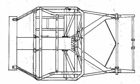
Chassis with Roll Cage Fitted (View from above – body removed)
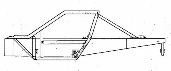
Chassis with Roll Cage Fitted (View from side – body removed)
The front suspension uprights and hubs were from the Triumph GT6 MK III to enable the use of larger 9 ¾ inch diameter brake discs and calipers from the same car.
The suspension arms inboard rubber bushings were changed to “Nylatron” (Moly Disulphide) bushings to eliminate any uncontrolled movement in the suspension. All bushings are identical and eight (8) are needed per car. The dimensions are: length = 1.40 inches; diameter = 1.061 inches with bore = 0.502 inches. The bushings are a “press-fit” in the suspension arms.
The suspension was lowered by fitting shorter front springs together with fully adjustable Knoi shock absorbers. It should be noted that due to the large deflections required in relation to spring length, special thin vanadium spring wire must be used to prevent the spring from becoming coil-bound on full bump. The shock absorber bump rubber must be shortened approximately one inch to prevent fouling on full bump.
With the lowered suspension settings, it is necessary to decrease the negative camber of the front wheels. This was achieved by moving the lower suspension arms’ outer pivot point inward. This was carried out by slotting the existing holes in the arms and installing drilled plates to locate pivot in desired position (0.158 inches per 1° of camber change). The plates fitting securely in channel of lower suspension arms.
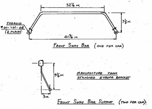
The optimum size of the front sway bar was found to be ⅞ inches in diameter. The bar was non-adjustable and installed in approximately the stock location. The sway bar had Fabroid rod end spherical bearings on each end and was attached to the lower shock absorber mounting bolts using spherical bearings. The standard location arms were shortened to compensate for the lowered suspension. (See Figure 2.1). All fine suspension tuning was achieved by use of an adjustable rear sway bar.
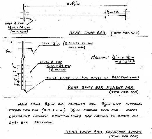
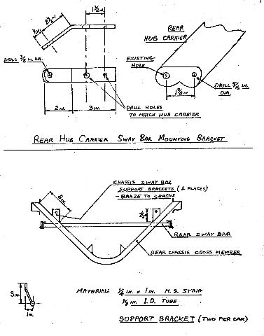
The modifications made to the rear suspension consisted of mainly eliminating rubber mounting bushings and strengthening chassis attachment points. Full adjustment capability was also provided. An adjustable sway bar was added to enable fine suspension adjustments to be made to compensate for different circuits. (See Figure 2.2A and 2.2B).
The trailing arms were relieved to provide clearance for the wide section Goodyear cantilever-type tires and wide wheels. The rubber chassis mounts were changed to “Fabroid” bearings and the trailing arms were modified to accept the Fabroid bearing rod-ends. Stiffening plates and reinforcement brackets were added to the chassis at the trailing arms attachment points. Care must be taken when installing the trailing arms to ensure there is enough angularity on the Fabroid bearings – tapered spacers and shimming washers between the bearings and the chassis are required. Wheel alignment is achieved by adding or removing shimming washers. (See Figure 2.3A and 2.3B).
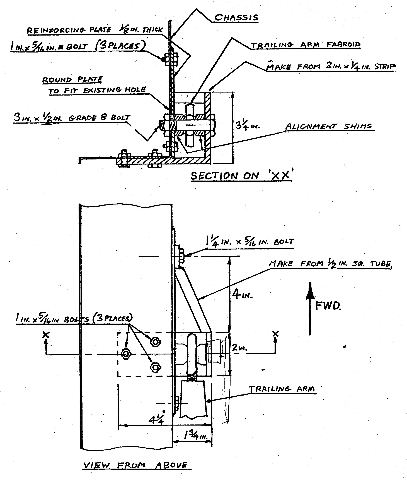
Trailing Arm Chassis Attachment Brackets
The rear stub axles were installed using “Loctite Shaft and Bearing Mount” on the threads. The locking nut was torqued to 160 lbs. ft. The hubs should be checked for tightness after every track session as problems have been experienced with stretching and consequent slackening of the axle shaft nut. It is recommended that the stub axles be replaced after three practice and race sessions as a precautionary measure.
The rubber bushings in the transverse links were replaced with Fabroid spherical bearing rod ends at each end. The rear wheel camber could be adjusted by changing the effective length of these transverse links. The inboard mount on the gearbox was strengthened to give more positive location.
Lowering of the rear suspension was achieved by using shorter springs and Koni shock absorbers. Approximately 1 inch of the bump rubber must be removed from the shock absorber to enable the lowest ride height to be used.
The standard steering rack was found adequate but it was found necessary to use Fabroid rod end spherical bearings on the tie rod ends. These bearings were installed on top of the steering arms together with shims to minimize bump steer. (See setting up section). The standard rack mounting brackets and location was retained. The column was lowered for increased driver comfort.
The standard vacuum assisted tandem master cylinder was replaced by separate non-assisted master cylinders fro the front and rear brakes. The two master cylinders were coupled by means of an adjustable, pivoted cross-bar to enable front to rear brake balance to be changed. Due to the proximity of steering rack, it was necessary to mount one master cylinder at 45° and utilize remote brake fluid reservoirs.
A new clutch and brake pedal assembly was fabricated to give improved pedal positions for heel and toe operation. A hydraulically operated clutch was used which employed a similar master cylinder and remote fluid reservoir.
The front brake discs were replaced by the 9 ¾ inch diameter discs from a Triumph GT 6 Mk III. This is a direct substitution of existing front uprights, hubs, calipers, etc., with those from the GT 6. Brake cooling was assisted by ducting air from air inlets in the front spoiler.
The rear brakes were changed to twin-leading shoe type with two wheel cylinders per brake. These brakes are approximately 40 percent more powerful and give the car more balanced braking. The back plates are of Girling manufacture and were standard fitment on the front of early Sunbeam Imp’s. (Similar backplates are found on the front of early Triumph Herald’s.) It was necessary to slightly modify the backplates so as to fit the 1 ½ inch width brake shoes and still maintain the desired rear track dimension. This entailed recessing center of plate approximately ⅛ inch closer to center of the car. (Same position as with standard backplates).
Aeroquip steel braided brake lines were used throughout and routed through the cockpit to prevent damage and facilitate inspection.
The standard radiator in conjunction with the engine oil coolers used was found to be adequate even when racing in ambient temperature as high as 115°F.
The electric fan was discarded and aluminum ducting fabricated to divert all airflow through the radiator. Aluminum tubing was substituted for the steel water tubes running through the chassis backbone. The 15 psi pressurized system utilized an expansion tank and 50 percent Ethylene Glycol coolant with inbitors. The system was filled through a threaded cap in the thermostat housing. The capillary type temperature gauge sensing bulb was mounted in the top radiator tank. Care must be taken to ensure all air is evacuated from the system.
It was found essential to use two front mounted oil coolers from an MGB (Part No. ARO 9809). The coolers were mounted in tandem in the side of the radiator ducting. The air from the coolers was ducted out underneath the car through an opening cut in the floor of the nose. (Consult SCCA GCR pertaining to oil cooler ducting limitations.)
The oil lines to the coolers were routed through the chassis backbone for safety purposes. A chassis mounted filter was used with the oil temperature being monitored at the filter head. The standard oil pump was retained with a higher relief valve setting.
The left headlight aperture was used for driver cooling (essential in high ambients) and to supply cooler air for engine breathing. A six inch duct was routed from the headlight opening through the cockpit, with an outlet for driver air and thence, through the firewall to a cold air box on the carburetors.
The capabilities and limitations of the Ford-based Lotus Twin-Cam are well known. Therefore, not attempt has been made to detail any engine modifications. the power output is severely restricted by the limited amount of substitution and modifications allowed under the SCCA Production sports rules.
All engine preparation was carried out by John Shankle of Shankle Automotive Engineering, Van Nuys, California, who we have always found to be extremely helpful and cooperative. The engine used was a non-emission controlled version utilizing twin Weber 40 DCOE carburetors with an eight-port cylinder head.
It was found necessary to increase oil-pan ventilation as there was a tendency for an excessive amount of oil to be pumped into the oil catch tank with the standard ventilation system. The problem was cured by and additional breather on the mechanical fuel pump blanking plate.
The four into one exhaust manifold was manufactured by Kurt Andress of Costa Mesa, California and featured a low mounted tail pipe length would protrude approximately six inches beyond the rear of the body, thus the tail pipe was routed to the left rear corner. This helps to minimize possible damage caused buy over exuberant competitors nudging the rear of the car.
A single plate, Borg & Beck competition clutch, was used in conjunction with a specially manufactured aluminum flywheel. A hydraulic actuating mechanism was employed in place of the standard cable system. This was found necessary due to excessive pedal pressure as a result of the stronger diaphragm spring of the competition clutch.
The master cylinder was mounted adjacent to the brake master cylinders on the front crossmember. A remote reservoir was necessary due to proximity of steering rack and radiator. (Car was R.H. drive). The slave cylinder was mounted on a fabricated bracket attached to the bell housing. It was necessary to shorten and rotate actuating arm approximately 180° to accept the adjustable pushrod from the slave cylinder. Ad adjustable stop was incorporated on the slave cylinder mounting bracket to prevent clutch overthrow. Clutch ventilation was increased by removing lower flywheel splash guard.
The spigot shaft supplied with the straight-cut, close-ratio gears has standard SAE splines to mate with the Borg & Beck clutch plate. If the standard spigot shaft is used it will be necessary to modify the center of the clutch disc to accept the metric splines. The easiest method is to weld the center from a standard disc into the Borg & Beck disc. The rivets were replaced by grade #9 bolts with slim nuts and machined heads for clearance. This method enables the same center to be used with several replacement clutch discs.
The standard throw-out bearing holder was retained by bolted to the actuating shaft instead of using roll pins. The slimmer profile of the competition clutch necessitated shimming the standard throw-out bearing ½ inch nearer the engine and installing a ⅜ inch thrust pad on the clutch cover. This single plate clutch, although rated for less power has performed very satisfactorily and only three discs were required for the complete racing season.
The transaxle of the Lotus Europa is of Renault manufacture and three types of gear boxes have been fitted.
The Type 336 transaxle contains mostly Renault but has several “Lotus-only” Renault parts. The most important difference is the opposite rotation of the crown wheel as opposed to the application sin Renault vehicle, due to the rear engine location of the Lotus.
The Types 352 and 365 transaxles are 100 percent Renault with no “Lotus-only” parts.
The Type 336 transaxle was used as the associated gear shift linkage is more precise and less vulnerable to damage in rear-end collisions. The five speed transaxle was not legal for SCCA racing in the 1972-1973 season.
Straight-cut, close-ratio gears were used with no synchromesh. It was necessary to relieve the transaxle casing to provide clearance for the input shaft third speed gear. A maximum end float 0f .005 inches is desirable in all gears and shims may have to be used to eliminate excessive end-float. All roll pins were safety wired for security.
The transaxle casing was drilled to accept 5/16 inch UNF bolts. The gearbox was assembled using Hylomar jointing compound.
No limited-slip differential was found necessary and the standard differential was used. The differential was assembled with .0005 inch end-float in each axle shaft. This was achieved by machining crown-wheel side of differential housing and replacing fiber washer with a brass washer of calculated thickness to give the required end-float. The latest type differential seals and caps were used (Renault No. 7700-554-257) with the cap threads sealed with Teflon tape. The drive shafts were attached with standard double roll-pins locked with safety wire.
The transaxle was mounted using a solid rear mount to prevent any uncontrolled movement due to suspension loads.
A slightly modified gear shift linkage was employed. The rubber mounted reaction bar on the gearbox was replaced by a solid bar with two spherical bearings. An additional bracket was mounted on the gearbox was replaced by a solid bar with two spherical bearings. An additional bracket was mounted on the gearbox casing. The linkage modified in this manner is very precise and fully adjustable at the gearbox.
A simple throw-over type reverse lock-out was employed at the gear-shift lever. It was found most desirable to adjust linkage so that the lever was hard against the lockout in third and fourth gear. This enabled fast, precise shifts to be made.
.. 1000 Pinion R.P.M. = 2.97 D divided by R MPH
Example where D= 20.5 inches and R = 3.56 :1

The excellent low drag and aerodynamic stability characteristics of the body shape eliminated the need for extensive modifications.
The fenders were flared and extended to provide the necessary clearance and shrouding required by the SCCA production sports car rules for the wider wheels and tires utilized.
High speed stability was improved by fitting a full width spoiler (available from Jensen Motors, Inc.) to increase down-thrust and prevent lifting of the front of the car. Ducts were provided in this spoiler to ensure adequate cooling air for the front brakes. It was necessary to reinforce the nose of the care to prevent sagging under racing stresses. The standard support plate was removed and support straps installed from the bottom of the front cross-member to the underside of the nose.
All redundant electrical equipment and other fittings were removed, together will all flammable trim items from the cockpit.
The vehicle was completely rewired utilizing interior and exterior master switches.
An aircraft-type battery was used mounted in approximately the original location but moved slightly for safety purposes due to proximity of fuel tank. The battery was placed longitudinally across the car adjacent to the engine bulkhead.
The European-type, single-arm, two speed wiper motor was used.
The mechanical fuel pump was replaced with a Stewart Warner electric pump, Model No. 240A and was mounted adjacent to the left-hand fuel tank. Aeroquip was used for all fuel lines.
On the left-hand fuel tank was used and the right-hand tank removed. An aircraft-type, anti-dump flapper valve was installed in the top of the tank to prevent fuel spillage if car was inverted.
The car used was a right-hand (R.H.) drive, British version. The R.H. driver location was chosen due to the clockwise rotation of most U.S. racing circuits.
The R.H. drive aspect is important in the layout of some components and this will be slightly altered in a left-hand (L.H.) drive vehicle. The roll cage installation should also be modified for L.H. drive.
There were no difficult adjustment or suspension tuning problems with the car constructed as previously described. The most difficult problem was the minimizing of front suspension bump-steer.
Bump-steer is dependent upon suspension geometry, ride height and effective steering rack location. It was not possible to completely eliminate bump-steer with the standard suspension geometry and steering rack location. An acceptable minimum was found to be ⅛ inch alignment change with suspension moving from full bump to full droop.
The adjustments used to minimize bump-steer were ride height and the effective position of the steering rack. The effective rack position was changed by adding shims between the steering arms and the Fabroid spherical bearing tie-rod ends. The ride height was adjusted to be the lowest possible consistent with minimum bump-steer.
The rear ride height was adjusted to give the minimum height needed to prevent the car bottoming on any particular circuit. All fine suspension tuning was by adjustments of the rear sway bar.
The setting-up specifications given were found suitable for most circuits and will provide an ideal starting point for extra-fine adjustments to “tailor” the car to suit a particular driver.
|
Girling - #3110243............................. .625 bore dia. |
||||
|
Girling - #64673467............................ 1 in. bore dia. |
||||
|
The many fabricated and modified parts developed for the Europa |
||||